Recently the Outernet team sent us a prototype of their L-Band tuned RTL-SDR which is called the SDRx for testing. This is an RTL-SDR with RTL2832U and R820T2 chips together with an L-band LNA and filter on the same PCB. It is designed for their Outernet system which transmits from geostationary L-Band satellites.
Outernet is an L-band satellite service that hopes to be a library in the sky. Currently it is broadcasting down about 20 MB of data a day, with data like weather updates, books, pictures, wikipedia pages, APRS repeats and more.
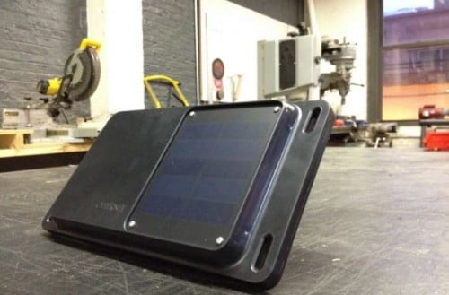
For their DIY Outernet kit they have been using E4000 or our RTL-SDR V3 dongles, so we speculate that this SDRx is going to be used in the “Lantern” which will be their fully assembled Outernet receiver product. The Lantern looks like it will be a single unit, with patch antenna, battery pack, solar panel, RTL-SDR radio and CHIP built into a plastic enclosure.
The upcoming RTL-SDR base Lantern Outernet Receiver.
The SDRx connects to the computer via a micro USB port. It also has a USB repeater and two USB expansion ports on board. This is useful as Outernet is designed to be used with the CHIP portable computer which only has one USB port. The expansion USB ports can be used for plugging in a portable hard drive which can be used as the storage for downloaded Outernet files.
We’ve been running a version of the SDRx prototype on an Outernet receiver for a number of weeks without issue. The SNR on Outernet signals is about identical to the V3 dongles combined with the external Outernet LNA and no L-band heat problems are observed.
The SDRx PrototypeUnder the shield. SAW Filter, R820T2. LNA top left.
GOES is an L-band geosynchronous weather satellite service that can be received typically with a satellite dish. It produces very nice full disk images of the earth. In the past we’ve posted about Lucas Teske’s work in building a GOES receiving system from scratch (including the software decoder for Airspy and RTL-SDR receivers), devnullings post about receiving GOES and also this talk by @usa_satcom on decoding GOES and similar satellites.
Over on Twitter @usa_satcom has been tweeting about his experiments where he has been successfully receiving GOES L-Band weather satellite images with a small grid antenna and an Airspy Mini. In a Tweet he writes that the antenna is an $85 USD Hyperlink 1.9 GHz 22 dBi Grid Antenna made by L-com. A grid antenna may be more suitable for outdoor mounting for many people as they are typically lighter, smaller and more suitable for windy and snowy conditions. As the GOES satellite is in geosynchronous orbit, no tracking motor or tracking mount is required.
GOES LRIT on small grid antenna? Sure, works just fine! Just a test setup for now. I'll post some FFTs and actual images later. pic.twitter.com/U6fALGCHl2
Back in October/November of last year Lucas Teske showed us how to receive weather satellite images from the GOES line of geostationary satellites with an Airspy SDR (and possibly an RTL-SDR too), dish antenna and the decoding software that he created.
On November 19, 2016 the next generation GOES 16 (aka GOES-R) satellite was launched by NASA. GOES 16 is a little different to the older GOES satellites as it has better sensors and is capable of capturing and transmitting a new image every 15 minutes which is quite fast. Thus a different and higher bandwidth RF transmission protocol called HRIT (High Rate Information Transfer) is used, compared to the LRIT (Low Rate Information Transfer) signal used on the older satellites.
Once the satellite started transmitting in January 2017, Lucas got to work on trying to create a decoder for the new satellite. After noticing some discrepancies between the published HRIT specs and the actual signal, Lucas sent off an email to NOAA and actually received an email back with the full specifications. With this information he was able to update his Open Satellite Project code and start decoding images from GOES 16.
The images being sent right now seem to just be relays of other similar satellites like Himawari-8 and Meteosat, as it seems that they are still testing the satellite. The relayed images received via GOES 16 received by Lucas can be seen on the Open Satellite Project twitter feed and on Lucas’ personal twitter feed.
Full disk image received via GOES 16, relayed from the Himawari-8 satellite.Weather data received via GOES 16.
Over on his blog author Manuel a.k.a ‘Tysonpower’ has written about a DIY Carbon Fibre Yagi antenna that he’s built for only 20€. The antenna is very lightweight thanks to a 12mm diameter carbon fibre pipe which is used as the main boom. It also uses 3D printed parts that clamp onto the carbon fibre pipe and hold the metal elements in place. The advantage of the carbon fibre pipe over a PVC one is not only is it lightweight and much easier to hold, but it also stronger, and much less bendy and floppy. The metal elements are welding rods which he found on eBay, and the carbon fibre pipe was sourced cheaply from China with Aliexpress.
A Yagi is a directional antenna with high gain towards the direction it is pointing. You’ll need to hand point the Yagi in the general direction of the satellite as it passes over, but you can expect much higher SNR readings compared to something like a QFH or Turnstile.
Manuel designed his antenna for 2M satellites (NOAA, Meteor M2, ISS etc), and was able to achieve over 36 dB SNR with an RTL-SDR.com V3 receiver, FM Trap and LNA4ALL on NOAA 18 at a 34° max. pass. He writes that the design is easily modifiable for other frequencies too.
To show off the design, construction and performance of his antenna he’s uploaded two videos to YouTube which we show below. The speech is in German, but even for non-German speakers the video is easily followed
Over on his blog Adam 9A4QV (seller of various RTL-SDR related goods including the LNA4ALL) has just made a post detailing a build of a high performance super simple NOAA/Meteor M2 weather satellite antenna. Most antenna designs for polar orbiting weather spacecraft are based on circularly polarized turnstile or QFH designs. However, Adams antenna is based on a very simple linearly polarized dipole, which makes construction almost trivial.
The idea is that by arranging a dipole into a horizontal ‘V’ shape, the radiation pattern will be directed skywards in a figure 0 (zero) pattern. This will be optimal for satellites travelling in front, above and behind the antenna. Since polar orbiting satellites always travel North to South or vice versa, we can take advantage of this fact simply by orienting the antenna North/South.
There is also another advantage to Adams design. Since the antenna is horizontally polarized, all vertically polarized terrestrial signals will be reduced by 20 dB. Most terrestrial signals are broadcast in vertical polarization, so this can help significantly reduce interference and overloading on your RTL-SDR. Overloading is a big problem for many trying to receive weather satellites as they transmit at 137 MHz, which is close to the very powerful FM broadcast band, air band, pagers and business radio. In contrast a circularly polarized antenna like a QFH or turnstile only reduces vertically polarized terrestrial signals by 3 dB.
As the satellites broadcast in circular polarization there will be a 3 dB loss in Adams design from using a linear polarized antenna. But this can be considered as almost negligible. Adam also argues that the home construction of a QFH can never be perfect, so there will always be at least a ~1dB loss from inaccurate construction of these antennas anyway.
The final advantage to Adams design is that construction is extremely simple. Just connect one element to the center coax conductor, and the other to the shield, and spread apart by 120 degrees.
Adam 9A4QV’s V-Dipole for 137 MHz Weather Satellites.
Adam has tested the antenna and has gotten excellent results. If you want more information about the antenna design, Adam has also uploaded a pdf with a more indepth description of the design and his thoughts.
UPDATE: Unfortunately we have been informed that the code base of this software was illegally decompiled and reused in an almost unchanged way from an already available closed source decoder. This means the program itself is illegal and totally unethical.
Please respect the original developers hard work and do not download this software.
A new STD-C Inmarsat decoder called —-Hz has recently been released. The decoder is Windows based and simply listens to the demodulated Inmarsat STD-C audio from a program such as SDR#. This means that it is compatible with the RTL-SDR, and any other SDR that can receive Inmarsat.
We gave the software a brief test and it ran very well, and managed to decode several SafeteNET messages without issue, maintaining a good lock most of the time. The author writes that he plans to improve on the software in the future by creating a web service based version of the software.
Currently there are two other Inmarsat decoders available. One is called InmarsatDecoder and the other is the Tekmanoid decoder. The InmarsatDecoder is generally regarded as the best, but the Tekmanoid decoder was recently updated for improved performance. The new software appears to be about the same as the Tekmanoid decoder.
Inmarsat STD-C messages are broadcast from geostationary satellites in the L-band at around 1.5 Ghz. They send mostly marine based messages such as the following quoted from the ——Hz website:
Safety: high seas, tropical storm warnings, ice accretion…
Shipping activity: moving oil rigs, submarine cable deployment and repairs…
Distress reports: MOB, ships lost at sea, migrant ship reports…
Military exercises (firing practice, no fly zones…)
Pirate at sea reports…
If you are interested in learning how to decode STD-C we also have a tutorial available here.
Recently RTL-SDR.com reader Mark wrote in and wanted to share his modified version of otti-soft’s GNU Radio flowgraph for decoding Meteor-M2 weather satellite images on Linux. The modified version allows for real time decoding, whereas the original version requires several offline decoding steps to be performed after recording the signal.
Mark writes:
I have modified one of otti-soft’s gnuradio flowgraphs so that they work with RTL-SDR and output the demodulated symbols to a TCP socket, from which the new version of LRPT Analizer (from robonuka.ru) can decode the data in real-time.
(AFAIK, only the AMIGOS version is able to decode the data from a socket, which is required for real-time decoding).
The program is to be run under a 32-bit version of Wine.
When the satellite is overhead, open and run the flowgraph (attached) in gnuradio-companion and leave it running. You might need to adjust the gain.
Then, run the LRPToffLineDecoder.exe executable from the extracted archive. It should display a constantly-updating constellation diagram. When the data is decoded, the channel images will start to appear in each section of the window.
That’s it, when the image is decoded, one can save it and close the windows of gnuradio-companion and the decoder.
Notes: when running the flowgraph, no other processes (rtl_sdr, rtl_power, gqrx, …) should use the SDR device.
The free versions of both decoders only decode the EGC broadcast messages which contain SafetyNET messages. These include messages like weather reports, shipping lane activity and hazards such as submarine cables and oil rig movements, pirate activity, refugee ship reports, missing ship reports, and military exercise warnings.
The paid version can decode the other non-broadcast private LES STD-C channels. LES STD-C channels typically contain email like messages sent to and from ships. Mostly it’s company messages about the ship route plans, cargo discussions, repair/fault discussions, ship performance information and weather reports etc. Sometimes small files are also downloaded. Each Inmarsat satellite contains about 7 LES channels each run by a different telecommunications company, so one may be of interest to you.
Tekmanoid STD-C Decoder Receiving LES Message.
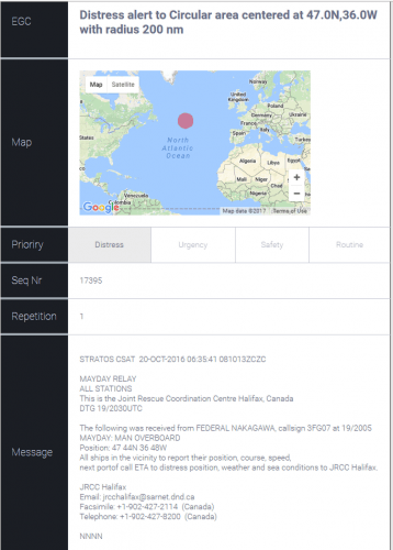
The paid version of the Tekmanoid decoder also has a nice feature for visualizing the SafetyNET EGC messages. Every now and then an alert containing coordinates and an area is sent out. Usually it is something like a distress alert from an EPIRB or the search area for a missing vessel. The decoder generates an HTML file that displays these areas on a map, alongside the text message.
STD-C EGC Distress Alert on map
The author of the Tekamnoid software allowed us to test his new paid version for free. We ran the software using signal from an Outernet patch antenna and LNA. An RTL-SDR V3 + SDR# was used as the receiver, and the audio was piped to the Tekmanoid decoder with VB-Cable. Decoding was almost flawless on both LES and EGC STD-C channels. In a previous recent update the Tekmanoid decoder was updated for improved decoding performance, and now in our opinion it is almost or just as good as the inmarsatdecoder.com software.
If you are interested in learning more about decoding Inmarsat STD-C we have a tutorial available here. LES channels for the Inmarsat satellite in operation over your geographic location can be found on UHF-Satcom’s website.
LES STD-C Inmarsat Channels
Remember that LES STD-C messages are not publicly broadcast, so in some countries it may not be legal to receive them. Most countries will have a law that says you can receive and decode the data, but you may not act upon or use to your advantage any information from the messages.
Over on the Thought Emporium YouTube channel the team have uploaded two videos that may be of interest to radio hobbyists. The first video shows a nice overview about receiving NOAA weather satellite images. They explain everything from scratch for complete novice, so the videos are great for almost anyone to watch and learn about radio and SDR concepts. The blurb of the first video reads:
Over the past 2 months, me and my friend Artem have been building antennas to receive signals from weather satellites as they pass overhead. This video chronicles our progress through this project and goes through some of the science involved in working with radio and receiving transmissions. We explore how dipoles work and how to build them, and how we built our final double cross antenna. We used an SDR (software defined radio) called a HackRF to do the work of interpreting the received signals and then decoded them with some special software. We pulled images from 4 satellites: NOAA 15, 18 and 19 as well as METEOR M2. The satellites broadcast immediately as they take the images and no images are stored, so we’re likely the only ones on earth with these images.
The second video is about building a radio telescope. Like the NOAA video, they explain all concepts in a simple and easy to understand way, so that anyone even without any radio knowledge can understand what the project is about. In the video they also show how they use a 3D printer to create a tracking mount which can point a satellite dish. They then use the dish to create a satellite heat map. The blurb reads:
Over the last 2 months me and my friend Artem (you met him in the last video) built our first radio telescope. It was built mostly out of off the shelf components, like a satellite dish and Ku band LNB, as well as some parts we 3d printed. When all was said and done we had a system that could not only take images of the sky in radio frequencies (in this case 10-12ghz), but could also be used to track satellites. With it, we were able to see the ring of satellites in geosynchronous orbit, over 35,000km away, This is only the first of what I suspect will be many more telescopes like this. Next time we’ll be building ones that are far larger and can see things like the hydrogen lines so we can image the milky way.
RF bypass for tuning from 24 – 1600 MHz – use as a regular RTL-SDR!
USB ports
GPIO forest
UARTs, I2C, SPI headers (unpopulated) for driving external hardware
Two microSD card holders – for boot and storage!
1 GHz CPU
256 MB RAM Now 512 MB RAM
USB wifi dongle (not shown) – STA+ AP mode capable!
Lots of LEDs! and Switches!
microUSB OTG
microUSB power port
Audio In/Out
Speaker with 1.4 W integrated audio amplifier
Fully mainline (4.10) Kernel and (2017.01) Uboot support! *** JST battery is being removed
On the Roadmap:
armbian/debian support
This is a fully-integrated SDR receiver – RF frontend, SDR, Compute, Wifi – Everything!
Outernet is an L-band satellite service that aims to be a download only “library in the sky”. Currently they are broadcasting from Inmarsat and Alphasat geostationary satellites which can be received from almost anywhere in the world. We have a tutorial on receiving and decoding their signal here. Every day almost 20 MB of data is sent down, and this includes data like news, weather forecasts, APRS, wikipedia articles, books and more. In the future you will be able to pay to upload private files or messages. This could be useful for sending messages to people isolated from cell phone reception, or for operating remote hardware.
Previously Outernet sold a DIY version of their receiver which included an RTL-SDR V3 or E4000 dongle, LNA+filter, a C.H.I.P embedded computer, and a patch antenna. Recently they have changed to their custom RTL-SDR hardware which is called the “SDRx”. The SDRx includes the RTL-SDR, LNA and filter on a single PCB. Over time it seems that they are moving in the direction of integration of all components onto a single PCB and this can be seen in the Dreamcatcher which now also includes the computing hardware. This is especially good news as the $9 C.H.I.P computing hardware has been almost impossible to acquire since its release.
The Dreamcatcher looks to be also not just useful for Outernet, but also for general projects that can be done on embedded hardware as there is a port which bypasses the L-Band filter.
Back in 2014 we posted about the XiOne. This was also to be an RTL-SDR and computing hardware built onto the same PCB. It would have been controlled via a WiFi connection and apps on a smart phone/tablet. Unfortunately the XiOne Indiegogo crowdfunding campaign never reached its target so the project faded away. The Dreamcatcher is somewhat similar in that both are RTL-SDRs with onboard computing hardware and WiFi connectivity.
The Dreamcatcher is not yet for sale, but it is currently under production. From the looks of the discussion on the forums, it looks like it will sell for $149 USD. Outernet have said that they are sending us a review sample, so keep an eye out for the review in the coming weeks.
The Outernet Dreamcatcher: RTL-SDR + LNA + Filter + Computing Hardware on a single PCB.
This software decoder appears to be an excellent choice for those people who want to perform their reception and decoding of Meteor M satellites all in Linux. Previously as explained in this previous post, you were able to receive the QPSK data in Linux with an RTL-SDR and a GNU Radio program, but then you’d still need to boot into Windows or run Wine to run LRPTofflinedecoder in order to generate the image. Now it appears that the image generation can be performed natively in Linux too with meteor_decoder. This help with creating portable automated Raspberry Pi based Meteor M decoder servers.
Meteor M is a class of Russian weather satellites that transmit live weather images of the earth as they pass over your location. They are somewhat similar to the NOAA satellites, although the Meteor satellites transmit higher quality images via a digital LRPT signal, rather than the analog APT signals used by NOAA. With an RTL-SDR, an appropriate antenna and decoding software they can easily be received.
An Example LRPT Image Received with an RTL-SDR from the Meteor M-N2 Satellite.
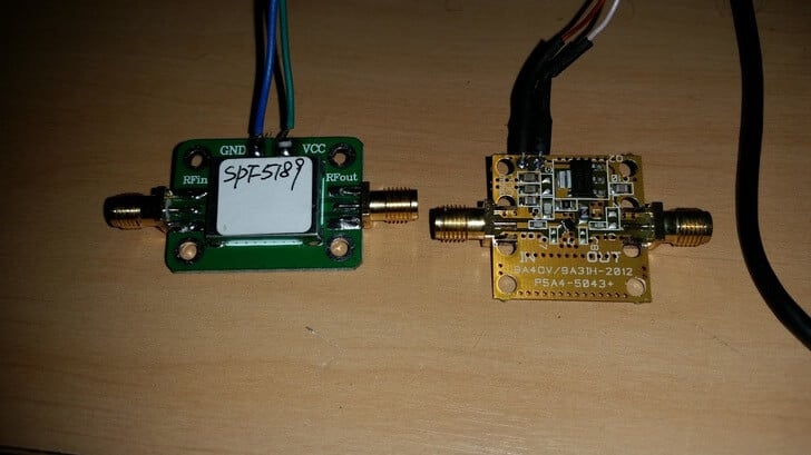
Over on his blog Lucas Teske has been comparing the LNA4ALL and an SPF5189 LNA from eBay on HRIT/LRIT reception from GOES satellites. SPF5189 LNA’s can be found on eBay for less than $8 USD, with free shipping from China, whereas the LNA4ALL costs 27 Euros shipped from Croatia. GOES is a geosynchronous orbit weather satellite which requires a satellite dish or other high gain antenna to receive. It downlinks at about 1.7 GHz, which means that a high quality LNA with low noise figure and good PCB design is needed for reception.
In his post Lucas mentions how he saw a review on eBay stating that the SPF5189 did not work at L-band. However, he found that odd as all of his SPF5189 LNA’s seemed to work just fine with L-band reception. So he did a benchmark comparing the SPF5189 to the PSA5043+ based LNA4ALL which is known to work well on L-band.
From his comparisons he found that the SPF5189 does indeed work well on L-band, and is comparable to the LNA4ALL. He concludes that the reviewer must have received a bad unit, or didn’t know what he was doing.
Lucas also makes an important note regarding the PCB design of these LNA’s. Even though the SPF5189 and PSA5043 chips have similar specs, with LNA’s the design of the PCB is crucial, as a poor design can significantly degrade performance. With the LNA4ALL you can be sure that the design is good, although the SPF5189 LNA’s currently on eBay look to be designed okay as well. Though with some eBay sellers there is no guarantee that you will receive a good board. We note that we have seen some really poor designs for PSA5043 LNA’s out there as well.
Thanks to Manuel (aka Tysonpower) for writing in and sharing his 3D printed ‘Universal Outernet Case’. Outernet is a satellite file casting service that uses an RTL-SDR based solution for reception. With an Outernet set up you can receive things like daily news, weather updates, books, Wikipedia pages and more all for free. About 20 MB of data can be transmitted in one day.
The DIY Outernet kit consists of an RTL-SDR ‘SDRx’ board, patch antenna and C.H.I.P single board computer. The patch antenna needs to point roughly in the direction of the Inmarsat/Alphsat satellite in your area. This can be a problem because the Outernet patch antenna doesn’t come with a stand or mounting solution.
Manuel solved this problem with his 3D printed Outernet enclosure. The enclosure houses the patch antenna, SDRx and C.H.I.P, and also doubles as a stand for pointing the patch antenna. Inside he’s also fitted a small 30mm fan to keep everything cool while inside the enclosure as the C.H.I.P is known to have overheating problems.
The 3D printed Outernet enclosure.
Over on YouTube Manuel has uploaded a video explaining how the enclosure is made with 3D printing, demonstrates the assembly steps and finally shows the final product. The video is narrated in German, but it has English subtitles available. The design files required for 3D printing the case are also available on thingiverse.
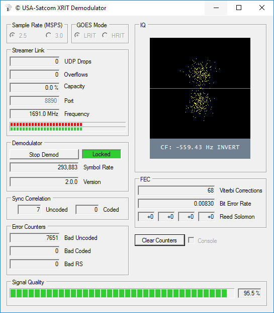
Over on his blog USA-Satcom has released his XRIT (LRIT/HRIT) decoder for GOES satellites. The software requires a licence and costs $100 USD. GOES-13 (East), GOES-15 (West) and the new GOES-16 are geosynchronous orbiting satellites that broadcast very nice high resolution weather images of the entire visible disk of the earth. The transmit their LRIT/HRIT signals at about 1.7 GHz at fairly weak power, which means that a good LNA and dish set up is critical to be able to receive them. A dish size of about 1 meter, or an equivalent grid or Yagi is recommended as the lowest starting point.
GOES Full Disk Image of the Earth
USA-Satcom’s decoder is Windows based and comes with a nice GUI. Some portions of the code are based on the Open Satellite Project created by Lucas Teske. It currently supports the Airspy R2/Mini and the SDRplay RSP2 software defined radios.
The software is not free, it costs $100 USD for the licence. To help curb illegal distribution of his software which has been rampant in the past, USA-Satcom also requests that you show some proof of a working setup which is capable of receiving the GOES signal before inquiring about the software.
If you are also interested, USA-Satcom did an interesting talk at Cyberspectrum a few months ago, and he has also recently uploaded his slides.
LilacSat-1 is an educational CubeSat built by students from the Harbin Institute of Technology (HIT) in China. It was recently launched from the ISS on 25 May 2017 as part of the QB50 science experiment to explore the lower thermosphere, and it is expected to stay in orbit for about 3 months. Apart from BPSK telemetry at 145.935 MHz, LilacSat-1 is interesting because it contains on board an FM to Codec2-BPSK digital voice amateur radio transponder at 145/436 MHz (uplink/downlink). It is probably the first amateur radio satellite to contain an FM to digital voice transponder.
To decode LilacSat-1 digital voice and telemetry you can use a Linux live CD provided by HIT, or download the GNU Radio decoder directly from the LilacSat-1 information page on the HIT website. The GNU Radio program can be used with any GNU Radio compatible SDR, such as an RTL-SDR.
An example of LilacSat-1 being decoded has also been uploaded by YouTube by Scott Chapman. In his test he used an RTL-SDR to work the pass live, but in the video shows an offline decoding received by his SDRplay which was also monitoring the same pass.
Back in March we posted about The Thought Emporium’s YouTube video that explained weather satellites and demonstrated that images could be downloaded from them using an SDR like a HackRF or RTL-SDR. Now The Thought Emporium have uploaded part two of the video series, which is a tutorial that shows exactly how to use the free software to receive, demodulate and decode NOAA and Meteor satellites.
The first part of the video shows how to use SDR#, Audacity and WXtoIMG to receive NOAA APT weather images. The second part of the video shows how to use SDR#, Audacity, LRPTrx, LRPTofflinedecoder, SmoothMeteor and LRPT processor to receive Meteor M2 LRPT images.
Over the last two weeks the QB50 experiment was launched from the International Space Station (ISS). The experiment consists of 36 cubesats built by various universities around the world, with the main science goal being to make measurements of the thermosphere (an upper atmospheric layer that the ISS orbits in). All the cubesats broadcast their telemetry in the 70cm (420 – 450 MHz) amateur band and they are expected to stay in orbit for about 3 months before falling back to earth. In a previous post we made a point to mention Lilacsat-1, which is one of the most interesting QB50 satellites due to its implementation of a FM to digital voice repeater on board.
Recently Outernet released their new ‘Dreamcatcher’ hardware which is an RTL-SDR + L-band LNA & filter + computing board all on the same PCB. The Dreamcatcher costs $99 USD and can be bought directly from their store. For your $99 you get the Dreamcatcher board, as well as a new ceramic L-band patch antenna which has a built in L-band LNA and filter. The built in LNA is useful as it allows you to use a few meters of extension cable in order to get the patch antenna in a good position outdoors.
At the moment the Dreamcatcher can be run with two different SD card images: the Skylark Outernet software, or Armbian (Linux). The Armbian image is basically just standard Armbian and at the moment does not actually run any Outernet software, and cannot decode their signal – but this is being worked on. Eventually they hope to depreciate the Skylark image and instead use an Outernet receiver app that runs on Armbian.
When running on the standard Armbian image, the Dreamcatcher can be used as a regular RTL-SDR connected to Linux, as there is a bypass port which bypasses the built in L-band LNA and filter. This port is enabled by default, but can be software switched to the L-band port if desired. There is also a 4.8V bias tee on the bypass port that can be turned on in software and used to power external devices via the coax cable. Currently there is no display support on the Dreamcatcher so the unit must be run headless, meaning that you must connect to it via UART or SSH from another PC.
The Outernet Dreamcatcher
The Dreamcatcher is advertised with the following specifications:
L-band SAW filter (1525 – 1559 MHz)
Two-stage L-band LNA with 34dB gain
1 PPM TCXO
RF bypass for tuning from 24 – 1600 MHz – use as a regular RTL SDR!
Software switchable bias tee
3 USB ports
GPIO forest
UARTs, I2C, SPI headers (unpopulated) for driving external hardware
Two microSD card holders – for boot and storage!
1 GHz CPU
512 MB RAM
USB wifi dongle (based on RTL8188CUS chipset) – AP mode capable!
Lots of LEDs!
Switches!
microUSB OTG
microUSB power port
Audio In/Out
Fully mainline (4.10) kernel and Uboot (2017.01) support!
Also as explained on the forums, Dreamcatcher uses an Allwinner A13 SoC, which has inside an ARM Cortex A8 @ 1 GHz CPU. They’ve also added 512MB of RAM. The PCB measures 12 cm x 12 cm.
Currently the Dreamcatcher is being advertised as beta hardware, as they give the following warning:
Although some assistance can be found on our forums, Outernet provides no direct support for this product. If you are not a tinkerer, hobbyist, or hardware hacker, you may be disappointed with your purchase.
The Dreamcatcher also comes with Outernet’s latest L-band patch antenna. The new patch antenna uses a ceramic patch and a 12 cm x 12 cm PCB ground plane. The antenna is ‘active’, as it has a built in L-band LNA and filtering. It is powered by the bias tee on the Dreamcatcher, and can also be powered by the bias tee on our V3 RTL-SDR’s. An active antenna is a good idea as this allows you to place the antenna outdoors (you’d need to waterproof this antenna in a plastic box though), and run a coax cable inside. The LNA should help overcome the coax cable loss which can be quite high at the L-band Outernet frequency of 1.5 GHz.
Outernet has provided us with a sample of this kit, and we plan to release a full review of the unit within the next few weeks.
Outernet active ceramic patch antenna (Front)Outernet active ceramic patch antenna (Rear)
Over on YouTube Adam 9A4QV has been testing out his HackRF and Portapack with his LNA4ALL. The LNA4ALL is able to be powered inline via the bias tee on the HackRF. In the first video Adam shows that the HackRF and LNA4ALL is capable of receiving L-band satellites easily. The antenna he uses is a homemade circularly polarized antenna with a cooking pot being used as the reflector.
Finally in the last video Adam shows himself making a full QSO contact using the HackRF, Portapack and LNA4ALL. The software he uses on the Portapack is Furtek’s ‘Havoc’ firmware which has microphone to TX functionality. The LNA4ALL is able to work in transmit mode without trouble. Adam has written instructions for modifying the LNA4ALL so that it can transmit and use the HackRF’s bias tee power at the same time over on his website lna4all.blogspot.com.
Last week we posted about Outernet’s new Dreamcatcher unit which is an RTL-SDR + L-band LNA + computing board all on the same PCB. The Dreamcatcher comes with a new active ceramic L-band patch antenna, costs $99 USD (plus shipping) and can be bought directly from their store. Outernet were kind enough to send us a review unit, and we’ve been testing it for the past few weeks. This post is a review of the unit.
Background
Outernet is a free data service that uses L-band satellites to beam down information like news, weather updates, Wikipedia articles, books and more.
In the past Outernet have used the $9 USD C.H.I.P computing board, an RTL-SDR dongle and an external LNA as the receiving hardware for their data service. However, popularity of the Outernet service has been severely hindered by the huge supply shortages of the C.H.I.P. Over the past year or so it has been almost impossible to get a hold of a C.H.I.P unit if you did not back the Kickstarter or buy one from Outernet’s first initial stock. By manufacturing their own PCB including the computing hardware, Outernet must be hoping to be able to control their stock situation, and not rely on third parties who may not be able to deliver.
At the moment the Dreamcatcher can only be run on their new Armbian image. The older Skylark image has been removed from their servers presumably because the Outernet signal is going to change in the near future and the old demodulator on Skylark may no longer work. The Armbian image is basically just standard Armbian and at the moment does not actually run any Outernet software, and cannot decode their signal, but this is being worked on. Eventually they hope to replace Skylark with a standard decoding app that runs on Armbian.
In this post we’ll review the Dreamcatcher with Armbian and consider it as a general purpose receiver (not just for Outernet), and we’ll also review the new active ceramic patch antenna as well.
Dreamcatcher Overview
The Dreamcatcher is a single PCB that combines an RTL-SDR, Linux (Armbian) based computing hardware, and an L-band LNA and filter.
On first impressions we noticed that the PCB is relatively large square at about 12 cm by 12 cm. The most prominent chip is the Allwinner A13 SoC. The RTL-SDR circuitry is positioned in the upper right with the RF sections (R820T and LNA) both covered with RF shielding cans. There is no onboard WiFi circuitry, but a small ‘EDUP’ branded WiFi dongle is included and plugs into one of the USB ports on the PCB.
We measured the Dreamcatcher to be using about 400 mA – 600 mA while idle and 800 mA while utilizing the RTL-SDR and 100% CPU. Heat is not an issue as the Dreamcatcher stays relatively cool during its operation even at 100% CPU with the CPU only getting up to about 45 degrees C.
Computing and Ports
The Dreamcatcher uses an AllWinner A13 System on Chip (SoC). Inside the AllWinner A13 is a single core ARM Cortex A8 CPU @ 1 GHz. The hardware is very similar to the hardware used on the C.H.I.P. Onboard the PCB is 512 MB of RAM, and there no onboard flash so everything is stored on an SD card.
There is space for two SD card slots on the board. One SD card is used for the Armbian Linux image, and the other can be used for data storage. There are also three USB-A ports available, but one is used up by the included WiFi dongle. There is one micro USB port for USB OTG and the another for power only. The USB OTG port can be used for the initial setup of the board, before it is connected to WiFi.
There are also audio and microphone input jacks available, breakout expansion pads for advanced users and some power/reset and boot setting switches.
RF Hardware
On board the PCB is circuitry for a single R820T2 based RTL-SDR with 1PPM TCXO. There are two SMA RF ports. One port is connected to the L-band LNA and filter which is to be used for Outernet or other L-band satellite reception with a passive patch antenna. The L-band port uses a 34dB gain LNA with L-band filter with a pass band of 1525 – 1559 MHz.
The other SMA port bypasses the LNA + filter so that the Dreamcatcher can be used as a general purpose RTL-SDR as well. A software controllable silicon switch is used to bypass the LNA + filter, so only one port can be used at a time. The bypass port also has a software switchable 4.8V bias tee which can be used to power the new active ceramic patch antenna from Outernet.
Dreamcatcher Setup
Setting up the Dreamcatcher involves burning their latest Dreamcatcher Armbian image to a microSD card, inserting the card, and then completing the setup via the UART connection. The full setup instructions are detailed in the image readme.txt file and in their operating manual available here. Various code snippets that show how to turn on the bias tee for example can be found here.
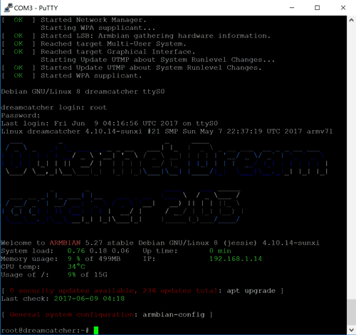
The full setup might take about 10 – 15 minutes, including burning the SD card. Once setup the Dreamcatcher should be connected to your WiFi connection, and then if you prefer you can SSH into it from a PC on your network using PuTTY or any other SSH software.
There are two ways to set up the UART connection on the Dreamcatcher. The first is to use the USB OTG port, and the second is to use a $1-$2 USB to UART adapter. The easiest is to use the USB OTG connection. To use it fist burn the image to an SD card, and then connect a USB cable from the USB OTG port on the Dreamcatcher to a USB port on your PC. The Dreamcatcher will be powered through the OTG port, and once the Dreamcatcher boots it will show up as a serial port on your PC. Now you can use a program like PuTTY to connect to that serial port.
The steps for using PuTTY to connect to the board are shown below.
Connect your USB to UART adapter to the UART1 pins, or the USB OTG port to your PC with a cable. If using USB OTG power the unit on now.
Now determine the COM port that you’re USB to UART adapter or USB OTG cable has been assigned by looking for the device in Device Manager.
Next in PuTTY choose “Serial”, enter the assigned COM port and set the baud rate to 115200. Then click Connect.
If using USB OTG the login prompt will now show. If using the UART adapter you can power up your Dreamcatcher and text should immediately begin scrolling in PuTTY. Wait for it to boot and reach the login prompt.
Now follow the instructions in the readme.txt file to setup the user accounts, and connect to WiFi.
The Outernet Armbian image comes with no software preinstalled, so after you login you’ll need to install the RTL-SDR drivers, and whatever software you want to run on it.
Dreamcatcher login on UART
Dreamcatcher Testing
Basic Software
First we tested the Dreamcatcher with some simple software like rtl_adsb which is automatically installed during the RTL-SDR install process. The first step was to connect an antenna to the LNA_bypass port. The bypass port is enabled by default, so no extra commands are needed to enable it. rtl_adsb was able to pick up aircraft with no problems.
Next we installed dump1090 and repeated the test. Again planes were picked up with no trouble. We also tested the dump1090 webserver, and we were easily able to connect to it from a networked PC.
Next we tested rtl_fm to see if we could get some audio out of the headphone jack. First we had to install sox with ‘apt-get install sox’. Then by default the volume is muted and turned down to zero so to unmute it, type in ‘alsamixer’. Use the arrow keys and the ‘m’ key to select all the devices and unmute them. Also turn up the volume on the power amplifier. With the sound unmuted rtl_fm ran well and could drive a speaker fairly loudly. The command we used was ‘rtl_fm -M wbfm -f 89.1M | play -r 32k -t raw -e s -b 16 -c 1 -V1 -‘
We also tested other software like rtl_433 which had no trouble running.
Currently Outernet have set up Howto’s for several applications including ADS-B, listening to FM broadcasts, setting up an APRS iGate, setting up Tight VNC which allows a networked graphical display, setting up YAAC APRS on Tight VNC, setting up WSPR reception, and using rtl_power for wideband spectrum analysis.
GR-Iridium & L-Band
We also tested gr-iridium on the Dreamcatcher which is software that allows you to listen to L-Band Iridium satellite phone calls and data. To actually get it to install we had to first set the Armbian package manager from Jessie to Stretch. This allowed us to download and install the latest version of GNU Radio from apt-get which is required for installing gr-iridium.
For reception we couldn’t use the new ceramic patch antenna because the SAW filter cut off is 1559 MHz and Iridium is at around 1625 MHz. Instead we used an LNA4ALL and the older Outernet metal patch antenna. We also tested the metal patch antenna with the onboard L-band LNA and this worked as well, although this is more difficult to use as a longer extension coax cable can’t be used unless you want lots of signal loss (since the LNA is not near the antenna). Iridium signals are often strong enough to be picked up even with a simple dipole, so that could work too if you can’t obtain a patch antenna.
We were able to get gr-iridium to run at 1 MSPS, but we ran into CPU limitations at anything higher which is unfortunate as gr-iridium really needs the bandwidth to cover as much of the Iridium band as possible. However, even with only 1MSPS we were able to receive and decode a very short 2 second call.
Unfortunately there is no software available for the Outernet signal or Inmarsat signals at the moment on Armbian, so we were unable to test these signals. Also JAERO for AERO signals is available for openSUSE 42.3, but not yet available on Debian systems. If anyone knows of any other Linux compatible L-band signal decoders please let us know in the comments. Outernet are planning to release an Armbian based decoder for their satellite service in the future.
Radio Data Streaming Software
Unfortunately, we started to run into some trouble when it came to running RTL-SDR streaming server software like rtl_tcp, SpyServer and OpenWebRX. In short none of those would work very well by default, however some tweaks were able to improve the situation.
With rtl_tcp we were only able to achieve stutter free operation at a 0.25 MSPS data rate. In comparison a Raspberry Pi 3 connected to the same WiFi network was able to easily handle at least 1 MSPS. It turns out that the ‘EDUP’ WiFi dongle that is included with the Dreamcatcher is quite slow, despite supporting 802.11n. Changing to a higher quality WiFi dongle allowed us to stream smoothly at 1 MSPS. The Outernet team have also reported to us that using an Ethernet adapter allows smooth streaming at 2.4 MSPS.
Next we tried the new SpyServer streaming software which is designed for Airspy SDRs, but also works with RTL-SDRs. The first problem we ran into was that the public SpyServer download did not run on the Dreamcatcher. We had to ask the SpyServer developer for a special version that was compiled for older CPUs. Once running SpyServer we sadly found that it would not run smoothly at any sample rate, with or without full IQ used. SpyServer uses less bandwidth compared to rtl_tcp, but here the problem was high CPU usage. The SpyServer does a lot of computations on the server side so the CPU usage is quite high. Unfortunately the CPU on the Allwinner A13 seems to be not powerful enough to run SpyServer.
We also tried OpenWebRX which is used for efficient remote streaming. See sdr.hu for various OpenWebRX SDRs shared on the internet. To save bandwidth OpenWebRX only sends waterfall data and compressed audio instead of full IQ data. But even at 0.25 MSPS the Dreamcatcher’s CPU struggled and was stuck at 100% CPU usage using the default config file. After tweaking the config file a little we were able to achieve smooth results at 1 MSPS, but only for one connection. Andras, the creator of OpenWebRX is working on some code optimizations for the Dreamcatcher which may improve performance in the future.
We think OpenWebRX might have trouble running on the Dreamcatcher’s Cortex A8 as it is a single core CPU, and OpenWebRX runs several threads. In comparison a Raspberry Pi 3 ran OpenWebRX easily and total CPU usage remained under 50%. This is because the Pi3 has a Cortex A53 @ 1.2 GHz, which is a 4 core CPU.
To get a handle on the CPU performance differences between the Pi 3 and Dreamcatcher CPU’s we ran sysbench on single thread, and on 4 thread mode using: ‘sysbench –test=cpu run’ and ‘sysbench –test=cpu –num-threads=4 run’.
Sysbench Dreamcatcher (1 Thread) – 286.584s
Sysbench Dreamcatcher (4 Threads) – 286.8299s
Sysbench RPi3 (1 Thread) – 182.3092s
Sysbench RPi3 (4 Threads) – 45.7500s
Sysbench shows that the Pi 3 is quite a bit faster, especially if all four cores can be utilized.
The Ceramic Active Patch Antenna
We also tested Outernet’s latest iteration of their L-band patch antenna. This new patch antenna uses a ceramic dielectric instead of an air gap which was used on their previous metal patch antenna. These ceramic patches are similar to the ones used in small GPS antennas, but larger.
The new patch antenna is also ‘active’, meaning that it has built into it a low noise amplifier (LNA) which must be powered via a 3-5V bias tee. The Dreamcatcher RF_bypass port has the required 4.8V bias tee to make it run. An L-band SAW filter is also built into the circuit and we assume the pass range (1525 – 1559 MHz) is the same as the filter used on the Dreamcatcher L-band port.
This new active patch antenna is a good idea as it allows you to use a run of a few meters of coax cable to get the antenna outside and into a good position where it can see the satellite.
We compared the new active ceramic patch with the previous metal patch + Outernet LNA combo using an RTL-SDR Blog V3 dongle with the bias tee powering the LNAs on both antennas. Signal levels were about 1-2 dB’s lower on the ceramic antenna, but we observed that the ceramic patch was slightly less directional and easier to point. We also tested with 2.5 meters of thin lossy RG174 coax and didn’t notice any loss in SNR. The LNA helps to boost the signal, so that signal losses in the coax are negligible.
Again, one issue with these antennas is that they have no mounting solution so we simply glued a 1/4 inch female thread onto the back of the PCB, and then used a standard camera suction cup to mount it on a window with a good view of the Inmarsat satellite. The antenna circuitry on the back is also not waterproof, so to waterproof the antenna it was later covered with a plastic sandwich bag. People who want to mount it more permanently might consider using a plastic lunchbox or other sturdier solution.
Active Ceramic Patch Antenna
Active Ceramic Patch Antenna (Rear) w/ our custom mount glued on
Active Ceramic Patch Antenna w/ our custom mount on window
Ceramic Patch
Ceramic Patch w/ 2.5M Extension
Metal Patch w/ Outernet LNA
Metal Patch w/ Outernet LNA & 2.5M Extension
Conclusion
So is the Dreamcatcher worth it? For $99 USD (plus shipping) about you’re getting a fully assembled compute board with RTL-SDR and L-Band LNA+filter module built in, as well as an active ceramic antenna. It is the first computing board that we know of that includes an RTL-SDR on the PCB itself. In the past projects like the XiOne attempted something similar, but never got off the ground.
Consider that a Raspberry Pi 3 costs $35, an RTL-SDR capable of receiving L-band like the V3 costs $20 and an Nooelec/Outernet L-Band LNA+SAW filter module costs $17.95. The Outernet metal patch antenna no longer seems to be for sale but that used to cost $25. The total price of those individual components adds up to $97.95 USD.
The Dreamcatcher is still a bit buggy, with problems regarding the streaming server RTL-SDR apps. And compared to the Pi 3 the CPU performance is quite a bit less, meaning that high CPU use software like OpenWebRX does not function that well. But regular apps that can run on the device like dump1090, rtl_433 etc all run just fine. In the future we’d like to see a more powerful CPU used as this would allow several more applications to run smoothly on the board.
In terms of product maturity, Outernet have put up a warning for potential buyers on their store which notes that the Dreamcatcher is “only for tinkerers, hobbyists and hardware hackers”, and that “no direct support for it is provided”. The most assistance available will be on their forums. To actually use the board you will need a decent understanding of Linux (being able to install and run software from the terminal), and preferably you’d need some previous experience with other small computing boards like the Raspberry Pi.
All in all the Dreamcatcher is a great buy for someone looking to get an all-in-one device, but it is still more suited to advanced experimenters. Hopefully the board soon matures, and we start to see actual Outernet apps appearing, as well as potential upgrades to the hardware as this will push the value of the board up significantly.